USAF XQ-2 and Q-2A Firebee exhaust layout


The research actually started off with a rather nerdy subject: the exhaust and exhaust area of the USAF Q-2A first-generation series production Firebee. I needed that information to correct the Lone Star Models 1/72 Q-2A Firebee model that I was working on, but photos showing that area were very difficult to find. No wonder since not a single example survived, as far as I know.


R&D phase first batch

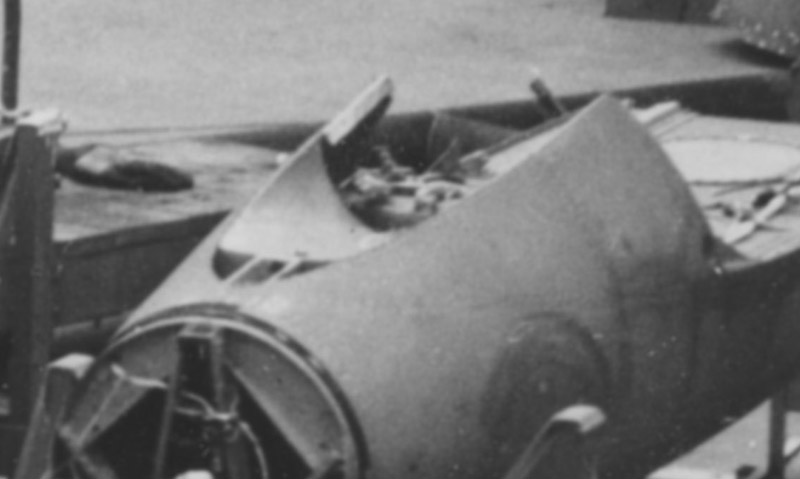
A detail view of the upside-down Firebee fuselage on the extreme right of the factory photo. It shows a deep concave cut-out, the center part of which is covered with sheet metal.
A detail view of the other upside-down fuselage, bottom left on the factory photo. It is roughly at the same manufacturing stage, but the circular hatch is absent, and the rivets are still visible.


USAF XQ-2 in the R&D phase, J44 powered

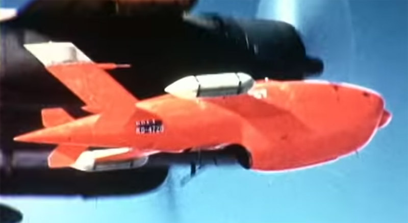
SDASM video F-2437 Ryan Firebee Launch from Douglas A-26 Invader shows another great view of this type of exhaust. I think I see a hint of a bullet projecting from the nose, making it a J44 powered USAF XQ-2.

The still shows an extra detail: either there is a stiffener mounted midway panel '1', or panel '1' consists of two panel with another (small) air gap.
In the next launch in the same SDASM video F-2437 Ryan Firebee Launch from Douglas A-26 Invader (shown mirrored), we can see the same exhaust details, and a starter/generator 'bullet' in the inlet, indicating a Fairchild J44 engine. Therefore it's an USAF XQ-2.

The white band over the fuselage suggests this is an Air Force example. The use of a DB-26 also supports this assumption of course.


USAF Q-2A series production, J69 powered

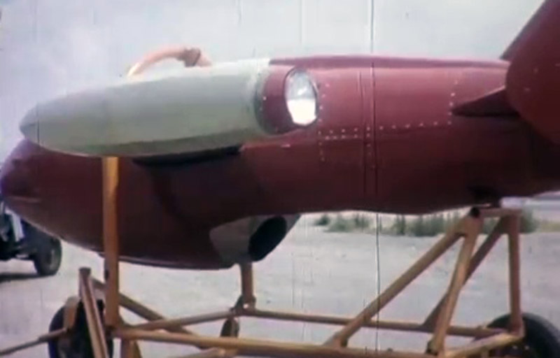
The series production Q-2A was powered by the Continental J69-T-19, with a distinct exhaust area. It's easy to spot since there's a bare-metal or silver-painted area at the end of the nacelle. This high-quality photo from the SDASM Archives (Q-2A Firebee AF-55-4798 on ramp, right side_3) shows this configuration well. Of note is that the the cut-out concave area is shorter: it now stops far ahead of the support bracket to mount it on the cart. Therefore a redesign of the rear fuselage must have taken place.

It has serial AF-55-4798. The use of 'DRONE' instead of 'TARGET' stencils also shows it's an Air Force Firebee.
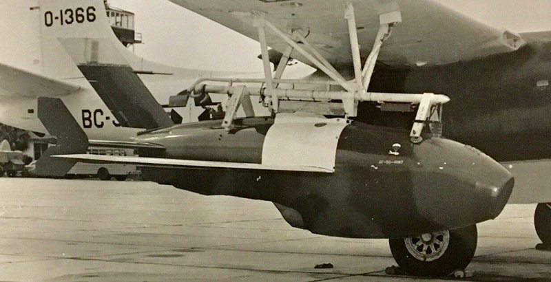
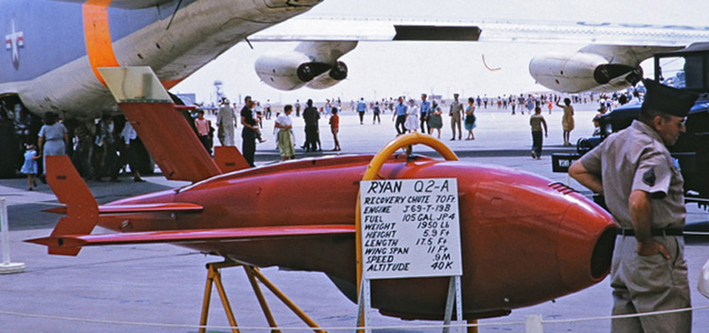
A photo from the internet, reportedly taken at a Kirtland air show in the sixties. The interesting bit is the sign telling us that the engine is a Continental J69-T-19B. Wagner says it was 880 lbs thrust. Compare that to the J69-T-29 in the larger Q-2C / BQM-34A that develops 1700 lbs. The T-29 had an additional axial compressor stage compared to the T-19. I've read that the T-19 is a copy of the Turbomeca Marbore, and the T-29 is a copy of the Turbomeca Gourdon, but that still has to be verified.

The '1957-1958 Aircraft Year Book' lists the following:
J69-T-19B, Continental Model 354-10. Specs: Length: 61.53 in. Width: 22.32 in. Total Weight: 317 lb. Compressor Stages: 1. Turbine Stages: 1. Performance: Takeoff thrust: 1060, SFC: 1.27, RPM: 21,700. Normal Thrust: 860, SFC: 1.25, RPM: 20,500.


Note the JATO collar attachment bracket on the parachute cone.
Another picture without a source, that shows the exhaust area reasonably well.
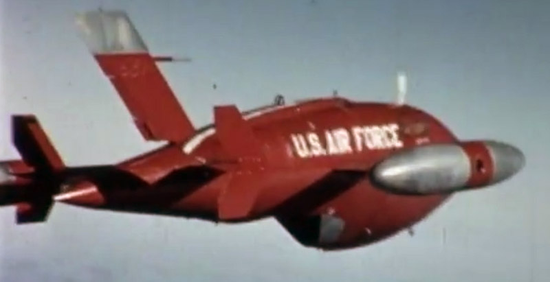
Great in-flight photo, with unusual 'U.S. Air Force' title on the fuselage, and no white band over the fuselage between the wings. Again it has the 'silver' area at the end of the nacelle. Source: SDASM video F-2619 'Operation William Tell' 1 1959 Ryan Firebee
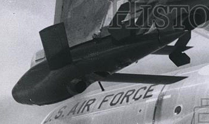
I lost the source, but I think we see exactly the same configuration here. Photo is dated 22 March 1960 on the back, the DC-130 is probably new. Or maybe called a GC-130A then.
Again a photo of which I lost the source, but showing the same configuration again. Note that the apparent step in the lower contour is caused by the skid ending where the 'silver' part begings.
Again I lost the source, but this view clearly shows the downsweep of the rear of the concave area, leaving a bit of circular (oval?) fuselage before arriving at the JATO attachment cut-out.
Screenshot from SDASM video F-2656 Ryan "Firebee" Q-2A Drone Douglas A-26, Convair F-102. Note later rectangular rear fuselage hatch. This Firebee is fitted with a 'rear facing lamp pod' according to the commentary.


Bits and pieces

Source: F-2666. Navy KDA, showing yet a different exhaust, large diameter exposed pipe.


USAF XQ-2 exhaust area study

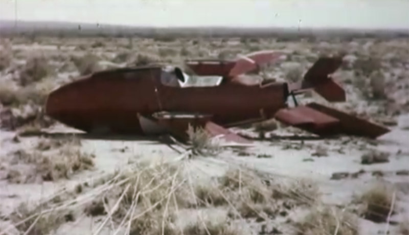
The SDASM video F-2718 Ryan RPV Firebee Accident Recovery shows a unique live landing of an USAF XQ-2 on a parachute, and then flipping over (12:24-12:36).

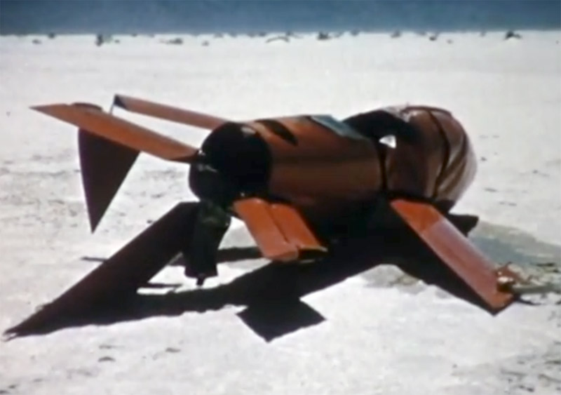
The way I see the exhaust area: the concave area is covered with two curved panels, that do not connect, but have an air gap. At the rear of the cut-out, an opening with a bracket is visible, just like in the factory photos.
Here's a drawing of what I think I see, sketched on the factory photo shown earlier. The mounting flanges for the forward concave panel (numbered '1' here) do not match the contour of the rear panel (2).
A still selected for maximum glare, in an attempt to see more details hidden in the shadows.
Part '3' is also visible in this screenshot from live landing film. And finally we can see that this Firebee has the starter/generator 'bullet' in the inlet, indicating a J44 engine, thus making it an USAF XQ-2.
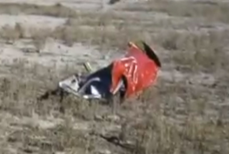
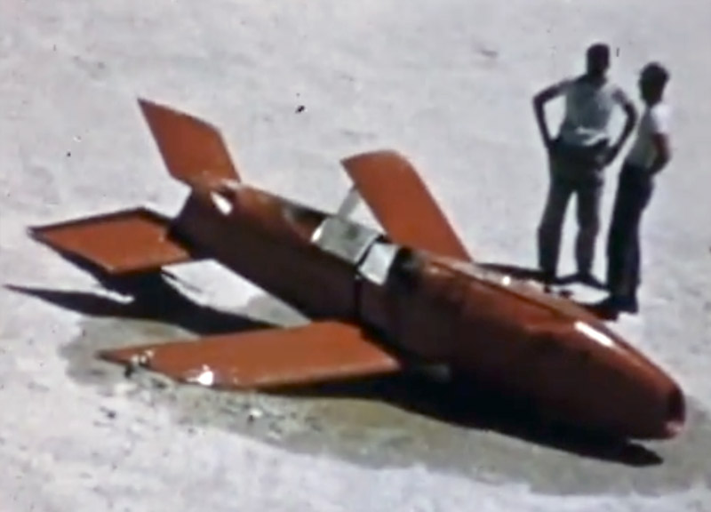
A still from the second crash scene from SADSM video F-2718, running from 08:05 to 11:00. It shows a Firebee on its back, with the nacelle ripped off, and the Fairchild J44 next to the wreck. The color scheme, red with a white band over the fuselage and wings, looks USAF to me; the Navy did not use a white band. Also there is no big Navy KDA-number under the horizontal tail. This would make it another USAF XQ-2.

It is difficult to see, but I think we can see the curved 'panel 1', right in the center of the photo. You can see its curvature on the forward edge. It is followed by a rather indistinct 'panel 2' and then the 'open bracket'. This all fits with the above pictures of J44 powered Firebees.
This looks like the ripped off nacelle, probably seen from the rear.


USAF Q-2A exhaust area study

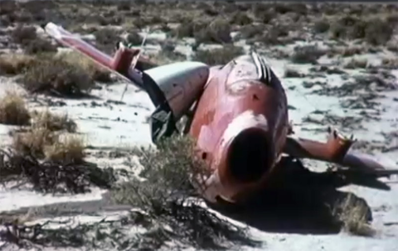
It was again a landing / crash video that showed the other details. The first crash scene in SADSM video F-2718 runs from 04:50 to 08:02. The various views of the wreck show the exhaust / rear fuselage configuration in perfect detail. The still are shown in the same sequence as in the film.

The footage is preceded by a card showing: '429-L / 10 Oct 56 / Coker'. This particular Q-2A has wing pylons and underwing stores, serial GM-54-1524, so it is definitely USAF-owned.

The SDASM photo archive on Flickr has three more photos of Q-2s with wing pylons and very large underwing stores: TRA 2-119 (serial GM-54-1521), 04_04215 (again serial GM-54-1521) and C-2-087. Only the first photo shows something of the exhaust area, and it is of the same type as that of the Q-2A shown here.
The oval inlet shape of the Q-2A is nicely shown here. The triple skids are noteworthy.
A nice clean view of the wreck, that clearly shows the flat panels behind the exhaust.

The endplates on the tailplanes are an interesting detail too. The are not symmetrical, and seem to be mounted in either position. Here the longer end was mounted upwards.
The next view from SADSM video F-2718. The triangular 'filler plates' next to the circular exhaust can be seen, and the width of the pylons can be judged here.
Here we see that the rear equipment hatch is of the later, rectangular type, demonstrating it's a series production USAF Q-2A.
Another view from SADSM video F-2718, that best shows the layout of the flat panels behind the engine exhaust. The belly panels have three angles. Also visible is the actual exhaust duct of the J69 engine.
Here's another botched landing, as seen in SADSM video F-2454. The lower rear fuselage shows the same details as in the previous photo series.
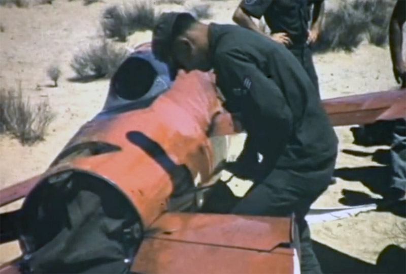
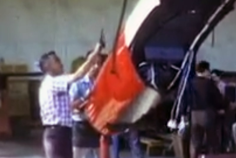
Another good view of the lower rear fuselage, with a crewman working on the avionics hatch on the left side of the fuselage.
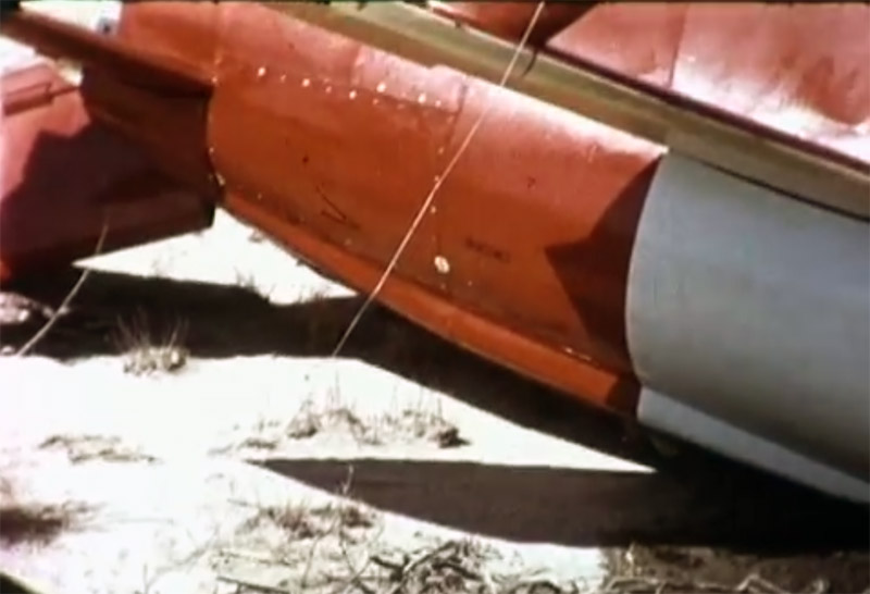
SADSM video F-2454 contains yet another failed landing. In this landing, the damage was more severe, and the bare metal panels behind the exhaust have become disconnected.
A rear view shows a buckling fold in the fuselage at the exhaust level.
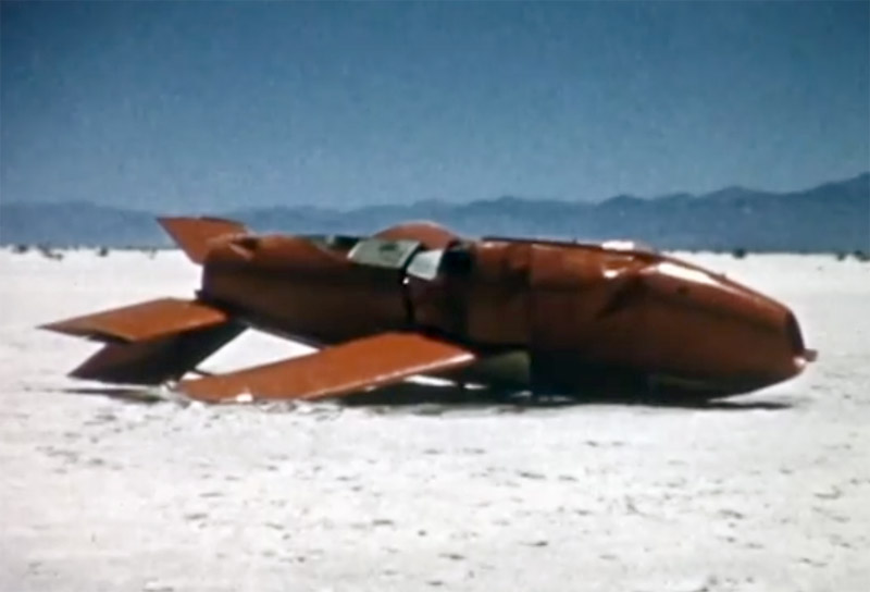
One last photo of this damaged Q-2A, with a good overall view of the exhaust area.


Type 3 exhaust area of USAF Q-2

Screenshot from SDASM video F-3047 Ryan Firebee Prep. Yet another shape, with a much wider bracket at the end of the concave cut-out.

Lots of J44 engines.
I think this is the same shape. Screenshot from SDASM video F-3047 Ryan Firebee Prep


Return to AQM-34 home page